Byers, J.A. 1981. Versatile electronic timer for synchronous switching of multiple electrical devices. Behavior Research Methods & Instrumentation 13:381-383. pdf

Electronic timer (at left), Noncircadian unit (at right) Abstract. An electronic timer consisting of CMOS integrated circuits is described that synchronously switches multiple electrical devices on and off on either circadian or noncircadian cycles. Precision is attained to within 1 min when used in the circadian mode or to within 16.7 msec when used at the highest speed (60 Hz). The electronic timer is useful for behavioral studies, control of environmental chambers, and control of general laboratory appliances.

Timers that switch electrical devices on and off are useful for automatic control of lamps, heaters, humidifiers, and other equipment in environmental chambers. Timers are also useful in many behavioral and physiological studies of organisms in which the presence or absence of various light, sound, temperature, and chemical stimuli in precise sequences and combinations is required.

Commercial timers are generally limited to only two on-off switches per day or, at most, to switching every other hour. Mechanical timers are motor driven, so that the exact moment of switching is difficult to adjust with precision, thus causing inaccuracy in synchronous switching of multiple electrical devices. An electronic timer using CMOS integrated circuits (ICs) for high reliability is described here that is relatively inexpensive and precise, with an adjustable cycle speed. The timer is easily programmed and can control an unlimited number of electrical devices on circadian and noncircadian cycles simultaneously.

METHODS AND MATERIALS

The schematic circuit of the electronic timer is shown in Figure 1. Main timer control unit
Figure 1. Electronic timer for synchronous control of multi- pte electrical devices. The timer will operate at 50 Hz (European) by connecting RE of IC 4 to Pin 1 instead of Pin 6 as shown.

A parts list for the timer, switching circuits (Figure 2), and noncircadian timer accessory (Figure 3) is shown in Table 1. Wire-wrap wire (30 AWG) was used for all connections. Wire-wrap sockets for IC chips were placed in a phenolic perforated board (2.54-mm hole spacing), and all connections were made before inserting the CMOS ICs. The CMOS IC chips and corresponding data sheets can be obtained from several electronic suppliers (e.g., Quest Electronics, Santa Clara, California; Jameco Electronics, Belmont, California). Pin numbers of ICs start at the upper left corner of the chip (top view) and run counterclockwise around the chip. The +12-V supply (VDD) is connected on all chips to the

Power circuit
Figure 2. Circuit controlled by timer for switching dc- (A) or ac- (A and B) powered devices.

upper right corner pin, and ground (VSS) is connected on all chips to the lower left corner pin. On the 4017 ICs, EN is Pin 13, RE is Pin 15, and CL is Pin 14; the other numbers next to each IC represent pin numbers. Unused inputs of the 4001 must be gounded, and unused inputs of the 4082 and 4081 must be connected to VDD. All resistors are 0.25 W. Each output of ICs 7-10 (Pins 3, 2, 4, 7, etc.) is connected to a red light-emitting diode (LED) and to 10 or more tie point terminals in an Experimentor sockets strip by Global Specialties
Table 1. List of Components Used in the Electronic Timer (Figure 1), "On-Off" Switching Circuit (Figure 2), and Noncircadian Timer (Figure 3)
Figure 1Figure 2Figure 3
Resistors
1 kohm11
1.5 kohm262
10 kohm1
20 kohm1
47 kohm1
CMOS Integrated Circuits
CD400111
CD401782
CD40751
CD40811*
CD40821+1*
Miscellaneous
SPST switch (NO)21
IN4001 diode41
Red LED262
470-microfarad capacitor1
2N2222 transistor (Q1)1
12-V ac transformer1
SCR 25-50 V (Q2)1
Triac 200-400 V (Q3)1
SPDT 12-V relay1
*The number of components shown must be doubled for each additional "on-off" circuit (Figure 2) needed.

Noncircadian optional circuit 
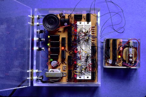
Figure 3. Noncircadian photoperiod timer (32 h). Connection of inputs of IC 16 to outputs of ICs 14 and IS determine the photoperiod (20 h light/12 h dark, as shown). A 32-day timer can be achieved by connecting the 1-kohm resistor of IC 13B to Pin 10 of IC 10 from Figure 1. Timers of 2-100 h or days can be achieved by utilizing all 10 outputs of each decade counter (see text).

(QT-59S from Jameco Electronics) or suitable substitute. Short pieces of 22- to 24- AWG wire are each connected by wire-wrap wire to an input of the four-input AND gate (IC 11, 4082). The short wire pieces are then inserted in the appropriate tie point terminals of the socket strip when programming the timer.

The outputs of the 4082 AND gates (IC 11) are connected to IC 12 in Figure 2 for electrical switch-on of an SCR (Q2) for dc applications, or triac (Q3) for ac applications, and connected to Transistor Q1 (npn 2N2222 or similar) for switch-off of the circuits by means of the SPDT relay. For each additional electrical device to be switched, the circuit in Figure 2 must be repeated. However, outputs from several AND gates may be coupled to the ON or OFF sections of a particular circuit, as shown in Figure 2, by three-input OR gates (4075), so that an electrical device may be switched at several different times during the day. The outputs of several OR gates may be combined by connection to OR gate inputs; however, only one OR gate output may connect to Q1 or Q2. Unused inputs of the OR gates must be grounded. In Figure 3, a noncircadian timer is shown, representing one of many possible cycle times. Other cycle times are possible, from 2 to 100 h or even days (Figure 3), by connecting the RE of ICs 14 and 15 to various outputs of these counters.


DISCUSSION

The timer circuit requires very little dc current, so that a 300-mA ac transformer, at 12 V (unregulated), is sufficient. The 60-Hz ac sinusoidal waveform is "squared" by ICs 1, 2A, and 2B to provide a time base for the sequence of CMOS decade counter/dividers that constitute the clock. IC 3 divides the incoming pulses by 10, IC 4 by 6 (by 5 for operation in Europe), IC 5 by 10, and IC 6 by 6, to provide I pulse/min to IC 7. The clock can be set to the correct time by the "slow" and "fast" set momentary switches.

During operation of the timer, 1 of the 10 LEDs from IC 7 lights for each minute, as does 1 of the 6 LEDs from IC 8 for each 10-min period of each hour. The CO (Pin 12) of IC 8 goes to ground once every hour and "clocks" IC 9, at which one of its six LEDs remains lighted for 1 h. A clock pulse every 6 h to IC 10 causes the four LEDs to light in sequence, each for 6 h, to repeat the cycle every 24 h. Therefore, at any particular minute of the day, only one set of four LEDs will be activated. If these outputs also are connected to a four-input AND gate, then the output of the gate will go "high" and trigger the OR gate or Q1 only at this particular time. The 22- to 24- AWG wire probes from a four-input AND gate are inserted into the tie points of the socket strip corresponding to the time desired to switch a certain electrical device.

Other devices may be switched from additional AND gates by connecting the output of these gates to inputs of OR gates, as in Figure 2. Any number of OR gates can be combined by connecting outputs to inputs of OR gates to control one SCR, triac, or relay. However, only one OR gate output should be connected to each of these electrical switches. A brief current pulse at the gate of the SCR or triac will cause it to turn on indefinitely. The power to an electrical device is then turned off by briefly interrupting current through the SCR or triac by means of a SPDT relay operated by Transistor Q1. A few types of electrical devices that self-interrupt current, such as alarm buzzers, must be controlled by a relay that, in turn, is controlled by the SCR.

In Figure 3, one example of a noncircadian timer that is similar in operation to the timer in Figure 1 is shown. The 32-h timer can be programmed in 1-h increments for any light-dark photoperiod from 1:31 to 31:1, depending on the connections of the inputs of IC 16 to the outputs of the two counters. Other timers of 2- to 100- h (or day) cycles can be made by utilizing various combinations of the 10 outputs of each 4017 counter and connecting RE to various outputs or to ground (for all 10 counts). The noncircadian timer is set by the "hours set" momentary switch until both LEDs are lighted. Output-to-input connections are then made between the decade counter (ICs 14-15) and two-input AND gates (IC 16) at the appropriate places for the desired photoperiod or switching times. The outputs of IC 16 are used to control OR gates in Figure 2 for switching electrical devices.

The timer (Figure 1) may be used at cycle speeds faster then 24 h by connecting the I-kohm resistor of the input to IC 2D to various outputs of ICs 3-6 and connecting their RE pins to various outputs of these counters. The fastest cycle speed that can be attained (from CL of IC 3) is 24 sec (at 60 Hz). This results in time increments of only 16.7 msec (corresponding to 1 min in the circadian mode).

Lewart (1979) described several circuits for switching appliances on and off that presumably could be controlled by a home computer. However, the necessary programs for operation were not given, since they would vary with the type of computer and application. Berenbon (1980) reported a program for a TRS-80 home computer that would control only one alarm on a 12- or 24-h cycle. However, more complex programs are necessary to switch on and off multiple electrical devices. These methods for timed control of electrical devices appear to make inefficient use of a home computer that probably could be put to more appropriate use. Furthermore, the interface circuits and programming would need to be different for each type of computer and application.

The electronic timer described here is versatile and can be used for any number of applications, from fraction collectors and noncircadian photoperiod timers to high-speed sequential release of behavioral chemicals and control of multiple environmental chambers.

JOHN A. BYERS

Department of Entomological Sciences, University, of Califomia, Berkeley, California 94720

Present address:

REFERENCES

Berenbon, H. Use your TRS-80 as a timer or alarm clock. Popular Electronics, 1980, 18(4), 72-73.

Lewart, C. R. Make your computer work as a control center. Popular Electronics, 1979, 16(3), 80-81.

home page